Physically Based Rendering – Part Three

Note : after several discussions in the team, I realized that some points were not clear in the “PBR for artists” post. I’ve made an update with additional information on how to handle metalness and specular. I invite you to read it.
Image Based Lighting in PBR
In Physically Based Rendering – Part Two, I talked about the basics of PBR for developers, and explained the different steps of the lighting process with PBR.
As said before, PBR does not necessarily imply to have indirect lighting, But that’s what makes it look so good.
Today I’m gonna focus on a technique called Image Based Lighting (IBL), that will allow us to cheaply compute this indirect lighting.
As before you can find at the end of the article a lexical with definitions of various unusual terms you’ll come across.
Indirect Lighting for PBR with Image Based Lighting.
Direct lighting is usually pretty clear for everyone as it uses common light sources (point light, directional light,…).
However indirect lighting is not that obvious. First you need to understand what we want to simulate with indirect light.
It is often referred as Global Illumination (or GI). This represents the light bouncing on surrounding objects that is lighting the shaded surface. There are several techniques to implement global illumination, but the most common is Image Based Lighting (IBL). It is very often associated with PBR pipelines.
So basically, a light source in game is a color, and optionally other parameters like direction, position, radius, etc… An image has color information, and this color can be considered as a light source.
For global Illumination light is coming from everywhere. So a good way to simulate GI with IBL is to consider an environment map as a light source.
Reminder on environment maps :
Most often, in-game environment maps are cube maps.
How do we fetch a pixel from an environment map? We need a vector. Often called the reflect vector (refVec), because that’s the reflection vector of the view direction on the shaded surface.
A picture worth thousand words
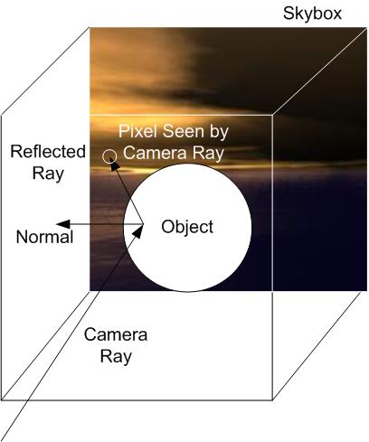
from wikipedia : TopherTH at the English language Wikipedia [GFDL (http://www.gnu.org/copyleft/fdl.html), GFDL (http://www.gnu.org/copyleft/fdl.html) or CC-BY-SA-3.0 (http://creativecommons.org/licenses/by-sa/3.0/)], via Wikimedia Commons Here the reflected Ray is our reflection vector.
Here the reflected Ray is our reflection vector.
Unfortunately we can’t take each pixel of the env map and compute light as if it was a direct light source and hope for the best.
There’s crazy math around that topic, and to be honest I didn’t get all of it myself. So instead of explaining difficult math equations that may be confusing, I’m gonna go straight to the point : How are we going to compute lighting from the environment map?
IBL Diffuse
First we need to compute Diffuse factor from the environment map. Remember our diffuse BRDF from last post? Lambert.
To simplify, Lambert diffuse BRDF, as it’s used in game, is the light color multiplied by a visibility factor.
This visibility factor is a function of the normal of the shaded geometry and the light direction.
Let’s say you have a direct light source lighting the front side of a geometry. The back side of this geometry is in the dark. Meaning the front side visibility factor is 1 and the back side visibility factor is 0.
For indirect lighting, we can ditch out this visibility factor because the light is coming from everywhere. So all of this simplifies in Diffuse factor = light color.
But what’s the light color for a given point?
Technically, every pixel in the environment map is a light source, so a shaded point is lighten by a vast amount of pixels.
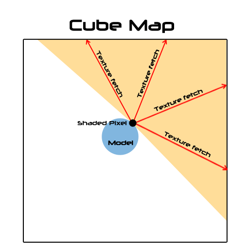
In this picture the orange area represent the light rays coming from the cube map to the shaded pixel, that we have to consider to properly compute the light color. So the idea would be, for each shaded pixel, to fetch all that texels and combine the colors.
As you can image that’s not practical for a real time rendering pipeline. Even with a 128×128 env map that’s around 50k texture fetches per pixel.
Fortunately, We can use something called an Irradiance map. An irradiance map is basically the afford mentioned computation…except that it’s precomputed and baked into a texture. In practice here is what it looks like.
On the left the original cube map, on the right, the pre computed irradiance map.
So at run time you just have to do one texture fetch in that map with the reflection vector. Pretty cool heh?
Except that to pre-compute that map we still have to sample the cube map literally billions of times, and even if it’s at design time…it’s painfully long.
Spherical Harmonics (SH) to the rescue
What’s that again? I won’t go into explaining them in details (because I can’t actually ;-P ), but just know that it’s once again some math magic with a big name on it. Here is a post where it’s explained with simple words, in terms of what you can use them for.
To put it simple, SH can help us to compute the irradiance map way faster. This article explains that it all boils down to compute only 9 spherical harmonics coefficients to efficiently approximate an irradiance factor.
At this point you can even skip the pre computation of the irradiance map, and use those coefficients directly in your shader for each shaded pixels. That’s fast enough to be real time, and use less memory than a cube map.
But still…it’s slower than one texture fetch, so I chose to compute the Irradiance map and use it in the shader.
With this technique I can compute a 128X128 irradiance cube map on the CPU in Java in about 200ms. Too slow to be done on each frame, but at design time that’s the blink of an eye.
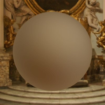
Here is the diffuse effect of indirect lighting using an irradiance cube map
IBL Specular
Indirect diffuse is cool, but we want “shiny”!! Shiny implies specular lighting.
It’s important to understand what we want as a specular reflection. We want it to be very neat when the roughness is low and very blurry when it’s high.
As roughness increase the reflection gets more blurry.
To do this, we have to resolve an integral called the radiance integral.
There is a method to do it quite fast that is called importance sampling. However it requires a lot of samples to get correct results, and therefore it’s pretty slow.
As an example, for the previous shot, I was using this method, with 1024 samples. It was barely interactive, because it ran at 16 fps on a GTX 670.
Thanks Epic games!
Epic games came with a solution to this issue for Unreal Engine 4. Others did too, actually, but Epic games made it public in this paper, from Brian Karis. I can’t thank them enough for this.
In this paper, they explain how they do it in UE4. They use a method they called the Split Sum Approximation. It doesn’t make the computation faster, but it transforms it so that it can be baked in two prefiltered textures.
-
The prefiltered environment map
We are going to pre process an env map on the CPU.
As explained before, we need the reflection to be more blurry as the roughness increase. The main idea here is to store different levels of roughness in the env map mip maps. The first mip map level will match roughness = 0 and the last will match roughness = 1.
From mip levels to mip levels we’re going to convolve (blur) the images depending on the roughness. The more the roughness increase the more samples we’re going to use, and the more spread out they will be.
But that’s not all, we also want to “bake” the specular BRDF in the map, so for each pixel we are going to compute the Cook-Torrentz microfacet BRDF (remember last post).
But, as we are preprocessing the map, we don’t have any information about the shaded surface normal and view direction. So we are going to assume they are all the same, and equal to the envVector we’ll use to fetch pixels from the map. Also we assume that the shading point is exactly at the center of the cube map.
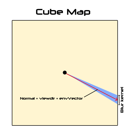
This is an approximation again, and it has a cost in quality, but we’re all for approximation as long as it’s perform faster while still looking good, right?
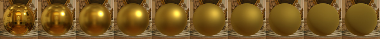
Here is what the result looks like
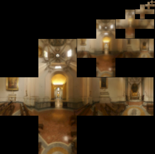
The prefiltered environment map, with the different mip levels. notice how the blur increases through them.
So now we can evaluate the first sum of the split sum approximation with a single texture fetch. We are going to compute the Lod level (the mip level where to fetch the texel) according to the roughness.
Note that the image needs to be set up so that textureCube interpolates linearly between mip maps so that if the roughness value is not right on the mip level, it will interpolate between the two closest mip levels.
-
The BRDF integration Map
Now we need the second sum of the split sum approximation.
It’s an integration that has two inputs, the roughness that varies from 0 to 1, and the dot product between the normal and the light direction (N.L, read N dot L) that also varies from 0 to 1.
The outputs are a scale, and a bias, also varying from 0 to 1.
So basically we can bake all combinations into a 2D map. roughness and N.L will be the texture coordinate. the red channel of the map will be the scale, and the green channel will be the bias. (the blue channel is not used)
Here is what it looks like :

The nice part is that this map is constant for white light. It does not depends on the environment. So you can bake it once and for all then use it as an asset in your shaders.
Now we have to combine values fetched from these maps to get the specular lighting.
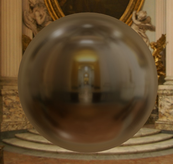
Here is what indirect specular alone, looks like, with a roughness of 0.1.
So in the end :
Our indirect lighting pseudo code looks like this :
//diffuse
indirectDiffuse = textureCube(IrradianceMap, refVec)  * diffuseColor

//specular
lod = getMipLevelFromRoughness(roughness)
prefilteredColor =  textureCube(PrefilteredEnvMap, refVec, lod)
envBRDF = texture2D(BRDFIntegrationMap,vec2(roughness, ndotv)).xy
indirectSpecular = prefilteredColor * (specularColor * envBRDF.x + envBRDF.y)

indirectLighting = indirectDiffuse + indirectSpecular
That concludes the post. Quite a lot of information to process. Now you should have an idea of the whole thing. Next time, we are going to go under the hood, and YOU GONNA HAZ CODE!!
Lexical :
Global Illumination (GI): A concept that represent all the lighting of a scene that is not coming from a direct light source.
Image Based Lighting (IBL): A technique that uses an image as a light source
Irradiance map : Precomputed environment map that contains diffuse lighting data of the environment.
Spherical Harmonics (SH): Read this
Importance Sampling : A math technique to approximate the result of an integral.
Split Sum Approximation : A way,used in Unreal Engine 4, to transform the specular radiance integral into 2 sums that can be easily baked into prefiltered textures.