3D Game Development Terminology
Before you start, make certain you are familiar with the following concepts and terminology.
3D Graphics and Audio
OpenGL is the Open Graphics Library, a platform-independent specification for rendering 2D/3D computer graphics. For Java, there are two implementations of OpenGL-based renderers:
-
Lightweight Java Game Library (LWJGL).
-
Java OpenGL (JOGL)
OpenAL is the Open Audio Library, a platform-independent 3D audio API.
Context, Display, Renderer
The jME Context makes settings, renderer, timer, input and event listeners, display system, accessible to a JME game.
-
The jME Display System is what draws the custom JME window (instead of Java Swing).
-
The Input System is the component that lets you respond to user input: Mouse clicks and movements, keyboard presses, and joystick motions.
-
The Renderer is what does all the work of calculating how to draw the 3D scenegraph to the 2D screen.
-
The Shader is a programmable part of the rendering pipeline. The jME3 game engine uses it to offer advanced customizable materials.
-
Geometry
Polygon, Mesh, Vertex
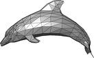
Most visible objects in a 3D scene are made up of polygon meshes – characters, terrains, buildings, etc. A mesh is a grid-like structure that represents a complex shape. The advantage of a mesh is that it is mathematically simple enough to render in real time, and detailed enough to be recognizable.
Every shape is reduced to a number of connected polygons, usually triangles; even round surfaces such as spheres are reduced to a grid of triangles. The polygons' corner points are called vertices. Every vertex is positioned at a coordinate, all vertices together describe the outline of the shape.
You create 3D meshes in tools called mesh editors, e.g in Blender. The jMonkeyEngine can load finished meshes (=models) and arrange them to scenes, but it cannot edit the mesh itself.
Materials: Color, Lighting/Shading
What we call “color” is merely part of an object’s light reflection. The onlooker’s brain uses shading and reflecting properties to infer an object’s shape and material. Factors like these make all the difference between chalk vs milk, skin vs paper, water vs plastic, etc!
Color
Reflections
Shininess
-
Degree of shininess of a surface (1-128).
-
Shiny objects have small, clearly outlined specular highlights. (E.g. glass, water, silver)
-
Normal objects have wide, blurry specular highlights. (E.g. metal, plastic, stone, polished materials)
-
Uneven objects are not shiny and have no specular highlights. (E.g. cloth, paper, wood, snow)
Set the Specular color to ColorRGBA.Black to switch off shininess.
Specular Color
-
If the material is shiny, then the Specular Color is the color of the reflected highlights.
-
Usually the same as the emissive color of the light source (e.g. white).
-
You can use colors to achieve special specular effects, such as metallic or iridescent reflections.
-
Non-shiny objects have a black specular color.
Materials: Textures
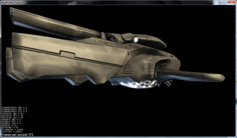
Textures are part of Materials. In the simplest case, an object could have just one texture, the Color Map, loaded from one image file. When you think back of old computer games you’ll remember this looks quite plain.
The more information you (the game designer) provide additionally to the Color Map, the higher the degree of detail and realism. Whether you want photo-realistic rendering or “toon” rendering (Cel Shading), everything depends on the quality of your materials and textures. Modern 3D graphics use several layers of information to describe one material, each mapped layer is a texture.
|
Got no textures? Download free textures from opengameart.org. Remember to keep the copyright notice together with the textures! |
Texture Mapping
-
Color Map / Diffuse Map
-
A plain image file or a procedural texture that describes an object’s visible surface.
-
The image can have alpha channels for transparency.
-
A Color Map is the minimum texture. You can map more textures as optional improvements.
-
Color Maps are unshaded. The same is called Diffuse Map in a Phong-illuminated material, because this texture defines the basic colors of light that are diffused by this object.
-
-
Bump Map
Bump maps are used to describe detailed shapes that would be too hard or simply too inefficient to sculpt in a mesh editor.
There are two types:
-
You use Normal Maps to model tiny details such as cracks in walls, rust, skin texture, or a canvas weave ( (More on BumpMaps).
-
You use Height Maps to model large terrains with valleys and mountains.
-
-
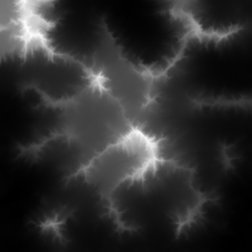
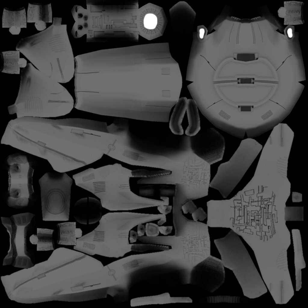
Height Map
-
A height map is a grayscale image looking similar to a terrain map used in topography. Brighter grays represent higher areas and darker grays lower areas.
-
A heightmap can represent 256 height levels and is mostly used to roughly outline terrains.
-
You can draw a heightmap by hand in any image editor.
-
-
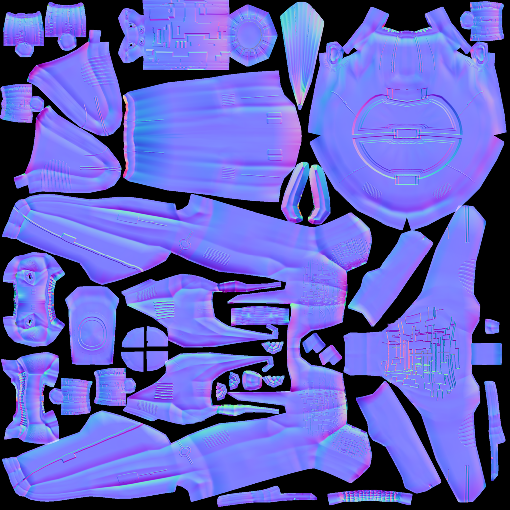
Normal Map
-
A well-done Normal Map makes a shape more detailed – without the need to add costly polygons to the mesh. It contains shading information that makes the object appear smoother and more fine-grained.
-
When you open a Normal Map in an image editor, it looks like a false-color version of the Color Map. Normal maps however are never used for coloring, instead, each the color values encode displacement data of bumps and cracks on the surface. Displacement data is represented by the Surface Normals of the slopes, hence the name.
-
You cannot draw or edit normal maps by hand, professional designers use software to calculate them off high-quality 3D models. You can either buy a professional texture set, or find free collections that include Normal Maps.
-
-
Specular Map
-
A Specular Map further improves the realism of an object’s surface: It contains extra information about shininess and makes the shape appear more realistically illuminated.
-
Start out with a copy of the Diffuse Map in a medium gray that corresponds to the average shininess/dullness of this material. Then add lighter grays for smoother, shinier, more reflective areas; and darker grays for duller, rougher, worn-out areas. The resulting image file looks similar to a grayscale version of the Diffuse Map.
-
You can use colors in a Specular map to create certain reflective effects (fake iridescence, metallic effect).
-
-
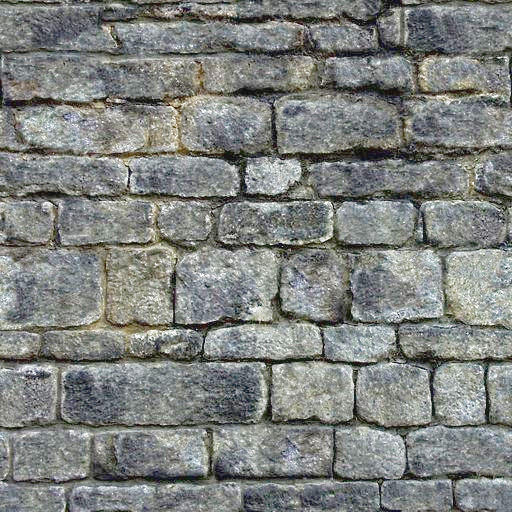
Seamless Tiled Textures
Tiles are a very simple, commonly used type of texture. When texturing a wide area (e.g. walls, floors), you don’t create one huge texture – instead you tile a small texture repeatedly to fill the area.
A seamless texture is an image file that has been designed or modified so that it can be used as tiles: The right edge matches the left edge, and the top edge matches the bottom edge. The onlooker cannot easily tell where one starts and the next one ends, thus creating an illusion of a huge texture. The downside is that the tiling becomes painfully obvious when the area is viewed from a distance. Also you cannot use it on more complex models such as characters.
See also this tutorial on How to make seamless textures in Photoshop.
-
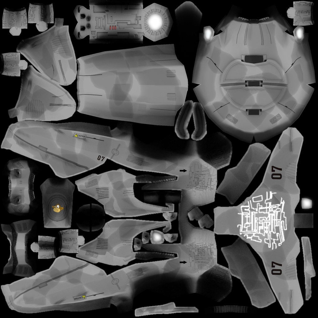
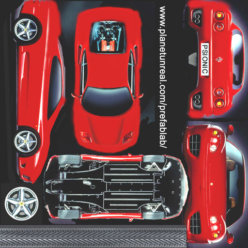
UV Maps / Texture Atlas
Creating a texture for a cube is easy – but what about a character with a face and extremities? For more complex objects, you design the texture in the same ways as a flat sewing pattern: One image file contains the outline of the front, back, and side of the object, next to one another. Specific areas of the flat texture (UV coordinates) map onto certain areas of your 3D model (XYZ coordinates), hence the name UV map. Using UV Maps (also known as Texture Atlas), one model can have different textures on each side. You create one corresponding UV map for each texture.
Getting the seams and mappings right is crucial: You must use a graphic tool like Blender to create UV Maps (Texture Atlas) and store the coordinates correctly. It’s worth the while to learn this, UV mapped models look a lot more professional.
-
Albedo Maps
Albedo maps are similar to Diffuse maps with the exceptions that they don’t have shadows or highlights. They are used as the base color of a PBR material.
Environment Mapping
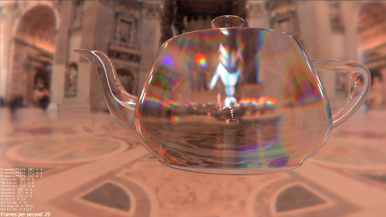
Environment Mapping or Reflection Mapping is used to create the impression of reflections and refractions in real time. It’s faster (but less accurate) than the raytracing methods used in offline rendering applications.
You create a Cube Map to represent your environment; Sphere Maps are also possible, but often look distorted. Basically you give the environment map a set of images showing a “360°” view of the background scene – very similar to a skybox. The renderer maps the environment on the texture of the reflective surface, which results in an acceptable “glass/mirror/water” effect. Just like a skybox, the reflection map is static, so dynamic things (such as the player walking) are not part of the reflection. (!)
See also: Water.
MIP Map Texture
MIP Map means that you provide one texture in two or three resolutions in one file (MIP = “multum” in parvo = “many” in one). Depending on how close (or far) the camera is, the engine automatically renders a more (or less) detailed texture for the object. Thus objects look detailed at close up, but also look good when viewed from far away. Good for everything, but requires more time to create and more space to store textures. If you don’t provide custom ones, the jMonkeyEngine creates basic MIP maps automatically as an optimization.
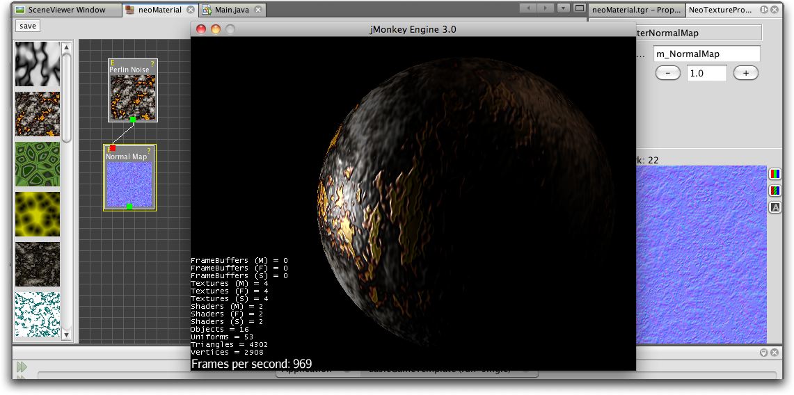
Procedural Textures
A procedural texture is generated from repeating one small image, plus some pseudo-random, gradient variations (called Perlin noise). Procedural textures look more natural than static rectangular textures, and they look less distorted on spheres. On big meshes, their repetitiveness is much less noticeable than with tiled seamless textures. Procedural textures are ideal for irregular large-area textures like grass, soil, rock, rust, and walls. Use the jMonkeyEngine SDK NeoTexture plugin to create them.
See also: Blender: Every Material Known to Man
Physically Based Rendering Textures (PBR)
Physically based rendering is an approach in computer graphics that seeks to render graphics in a way that more accurately models the flow of light in the real world.
To simplify, PBR attempts to deliver photo realistic images based off the texture of a material and how light becomes more reflective the more you view it at an angle. In other words, it’s based on real physics. Everything has a reflection but accurately representing that reflection in video graphics has been mostly done with tricks prior to the introduction of PBR. Tricks as in using different lighting images (specular maps) overlaying color images (diffuse maps) to simulate shininess.
With PBR, a materials “Metalness” (conductive) or "Dielectric" (insulator) and "Roughness" or lack thereof will determine how light gets reflected. For example, metal (Metalness) is smoother than dirt (dielectric) so has a higher reflection whereas the dirt would tend to absorb the light, just as in real world conditions.
The technique described above is known as the “Metalness Workflow”. Where you are deciding whether the texture is metallic or dielectric and defining the amount of roughness for the texture.
There is another workflow known as the “Specular Workflow”. In the metalness workflow the albedo map is used for both diffuse color and specular color. “Specular Workflow” uses a specular color map instead. In this workflow, the albedo map is the diffuse color, the specular map is the specular color, and you have a gray scale gloss map that is the same as the roughness map. The workflow is very similar to the old techniques used for making materials.
This has been a brief introduction to PBR. In reality, it requires a significant amount of learning to implement correctly. Read the three part series of articles called, Physically Based Rendering, that can be found under the “Material, light, Shadow” topic for a more in depth explanation of PBR textures. This is a must read for any serious jME developer.
See also: Understanding Metalness.
You should also conduct many searches on the subject, especially ones related to your modeling tool of choice.
Animation
In 3D games, Skeletal Animation is used for animated characters, but in principle the skeleton approach can be extended to any 3D mesh (for example, an opening crate’s hinge can be considered a primitive joint).
Unless you animate a 3D cartoon, realism of animated characters is generally a problem: Movement can look alien-like mechanical or broken, the character appears hollow, or as if floating. Professional game designers invest a lot of effort to make characters animate in a natural way, including motion capture.
Rigging and Skinning
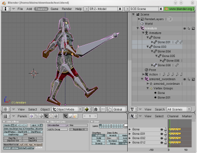
An animated character has an armature: An internal skeleton (Bones) and an external surface (Skin). The Skin is the visible outside of the character and it includes clothing. The Bones are not visible and are used to interpolate (calculate) the morphing steps of the skin.
JME3, the game engine, only loads and plays your recorded animations. You must use a tool (such as Blender) to set up (rig, skin, and animate) a character.
-
Rigging: The Construction of a character’s skeleton.
-
Create as few Bones as possible to decrease complexity.
-
Bones are connected in a parent-child hierarchy: Moving one bone can pull another bone with it (e.g. arm pulls hand).
-
Bones follow a certain naming scheme so the 3D engines know what’s what.
-
-
Skinning: The association of individual bones with the corresponding skin sections.
-
Each Bone is connected to a part of the Skin. Animating the (invisible) Bone pulls the (visible) Skin with it.
E.g. the thigh Bone is connected to the upper leg Skin. -
One part of the Skin can be affected by more than one bone (e.g. knee, elbow).
-
The connection between bones and skin sections is gradual: You assign weights how much each skin polygon is affected by any bone’s motion.
E.g. when the thigh bone moves, the leg is fully affected, the hips joints less so, and the head not at all. -
jMonkeyEngine supports hardware skinning (on the GPU, not on the CPU).
-
-
Keyframe Animation: A keyframe is one recorded snapshot of a motion sequence.
-
A series of keyframes makes up one animation.
-
Each model can have several animations. Each animation has a name to identify it (e.g. “walk”, “attack”, “jump”).
-
You specify in your game code which keyframe animation to load, and when to play it.
-
|
What is the difference between animation (rigging, skinning, keyframes) and transformation (rotation, scaling, moving, “slerp”)?
|
Kinematics
-
Forward kinematics: “Given” the angles of all the character’s joints, what is the position of the character’s hand?
-
Inverse kinematics: “Given” the position of the character’s hand, what are the angles of all the character’s joints?
Controller and Channel
In the JME3 application, you register animated models to the Animation Controller. The controller object gives you access to the available animation sequences. The controller has several channels, each channel can run one animation sequence at a time. To run several sequences, you create several channels, and run them in parallel.
Artificial Intelligence (AI)
Non-player (computer-controlled) characters (NPCs) are only fun in a game if they do not stupidly bump into walls, or blindly run into the line of fire. You want to make NPCs “aware” of their surroundings and let them make decisions based on the game state – otherwise the player can just ignore them. The most common use case is that you want to make enemies interact in a way so they offer a more interesting challenge for the player.
“Smart” game elements are called artificially intelligent agents (AI agents). An AI agent can be used to implement enemy NPCs as well as trained pets; you also use them to create automatic alarm systems that lock doors and “call” the guards after the player triggers an intruder alert.
The domain of artificial intelligence deals, among other things, with:
-
Knowledge – Knowledge is the data to which the AI agent has access, and on which the AI bases its decisions. Realistic agents only “know” what they “see and hear”. This implies that information can be hidden from the AI to keep the game fair. You can have an all-knowing AI, or you can let only some AI agents share information, or you let only AI agents who are close know the current state.
Example: After the player trips the wire, only a few AI guards with two-way radios start moving towards the player’s position, while many other guards don’t suspect anything yet. -
Goal Planning – Planning is about how an AI agent takes action. Each agent has the priority to achieve a specific goal, to reach a future state. When programming, you split the agent’s goal into several subgoals. The agent consults its knowledge about the current state, chooses from available tactics and strategies, and prioritizes them. The agent repeatedly tests whether the current state is closer to its goal. If unsuccessful, the agent must discard the current tactics/strategy and try another one.
Example: An agent searches the best path to reach the player base in a changing environment, avoiding traps. An agent chases the player with the goal of eliminating him. An agent hides from the player with the goal of murdering a VIP. -
Problem Solving – Problem solving is about how the agent reacts to interruptions, obstacles that stand between it and its goal. The agent uses a given set of facts and rules to deduct what state it is in – triggered by perceptions similar to pain, agony, boredom, or being trapped. In each state, only a specific subset of reactions makes sense. The actual reaction also depends on the agent’s, goal since the agent’s reaction must not block its own goal!
Examples: If player approaches, does the agent attack or conceal himself or raise alarm? While agent is idle, does he lay traps or heal self or recharge magic runes? If danger to own life, does the agent try to escape or kamikaze?
More advanced AIs can also learn, for example using neural networks.
There are lots of resources explaining interesting AI algorithms:
Math
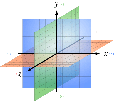
Coordinates
Coordinates represent a location in a coordinate system. Coordinates are relative to the origin at (0,0,0). In 3D space, you need to specify three coordinate values to locate a point: X (right), Y (up), Z (towards you). Similarly, -X (left), -Y (down), -Z (away from you). In contrast to a vector (which looks similar), a coordinate is a location, not a direction.
Vectors
A vector has a length and a direction, like an arrow in 3D space. A vector starts at a coordinate (x1,y1,z1) or at the origin, and ends at the target coordinate (x2,y2,z2). Backwards directions are expressed with negative values.
Example:
Vector3f v = new Vector3f( 17f , -4f , 0f ); // starts at (0/0/0)
Vector3f v = new Vector3f( 8f , 0f , 33f ).add(new Vector3f( 0f , -2f , -2f )); // starts at (8,-2,31)
Unit Vectors
A unit vector is a basic vector with a length of 1 world unit. Since its length is fixed (and it thus can only point at one location anyway), the only interesting thing about this vector is its direction.
-
Vector3f.UNIT_X= ( 1, 0, 0) = right -
Vector3f.UNIT_Y= ( 0, 1, 0) = up -
Vector3f.UNIT_Z= ( 0, 0, 1) = forwards -
Vector3f.UNIT_XYZ= 1 wu diagonal right-up-forwards
Negate the components of the vector to turn its direction, e.g. negating right (1,0,0) results in left (-1,0,0).
Normalized Vectors
A normalized vector is a custom unit vector. A normalized vector is not the same as a (surface) normal vector. When you normalize a vector, it still has the same direction, but you lose the information where the vector originally pointed.
Example: You normalize vectors before calculating angles.
Surface Normal Vectors
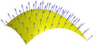
A surface normal is a vector that is perpendicular (orthogonal) to a plane. You calculate the Surface Normal by calculating the cross product.
Cross Product
The cross product is a calculation that you use to find a perpendicular vector (an orthogonal, a “right” angle at 90°).
In 3D space, speaking of an orthogonal only makes sense with respect to a plane. You need two vectors to uniquely define a plane. The cross product of the two vectors, v1 × v2, is a new vector that is perpendicular to this plane. A vector perpendicular to a plane is a called Surface Normal.
Example: The x unit vector and the y unit vector together define the x/y plane. The vector perpendicular to them is the z axis. JME can calculate that this equation is true:
( Vector3f.UNIT_X.cross( Vector3f.UNIT_Y ) ).equals( Vector3f.UNIT_Z ) == true
Transformation
Transformation means rotating (turning), scaling (resizing), or translating (moving) objects in 3D scenes. 3D engines offer simple methods so you can write code that transforms nodes.
Examples: Falling and rotating bricks in 3D Tetris.
Slerp
Slerp is how we pronounce spherical linear interpolation when we are in a hurry. A slerp is an interpolated transformation that is used as a simple “animation” in 3D engines. You define a start and end state, and the slerp interpolates a constant-speed transition from one state to the other. You can play the motion, pause it at various percentages (values between 0.0 and 1.0), and play it backwards and forwards. JavaDoc: slerp()
Example: A burning meteorite Geometry slerps from “position p1, rotation r1, scale s1” in the sky down to “p2, r2, s2” into a crater.