Creating assets in Blender3D
This section discusses how to create and import models from Blender3D (2.78+, see bottom of page for Blender 2.49 and before) to jME3. Furthermore, it explains how you can create various typical game-related assets like “Normal” maps of high-poly models and “Baked Lighting” maps.
Asset Management
For the managing of assets in general, be sure to read the Asset Pipeline Documentation. It contains vital information on how to manage your asset files.
Creating Models
Game-compatible models are models that basically only consist of a mesh and UV-mapped textures, in some cases animations. All other material parameters or effects (like particles, etc.) cannot be expected to be transferred properly and probably would not translate to live rendering very well anyway.
UV Mapped Textures
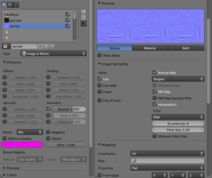
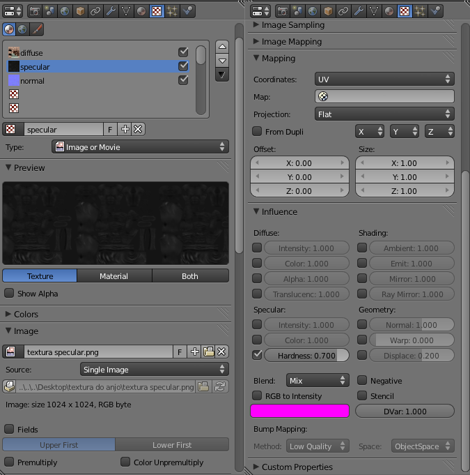
To successfully import a texture, the texture has to be UV-mapped to the model. Heres how to assign “Diffuse”, “Normal” and “Specular” maps:
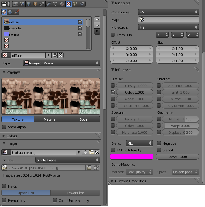
It’s important to note that each used texture will create one separate geometry. So it’s best to either combine the UV maps or use a pre-made atlas with different texture types from the start and then map the uv coords of the models to the atlas instead of painting on the texture. This works best for large models like cities and space ships.
Animations
Animations for jME3 have to be bone animations, mesh deformation or other forms of animation are not supported.
To create an animation from scratch do the following:
-
Create the model.
-
Make sure your models location, rotation and scale is applied and zero / one (see “Model Checklist” below).
Did you know? You can make any model from a box by only using extrusion, this creates very clean meshes.
-
-
Create the armature bones, don’t forget to have one root bone!
-
Start by placing the cursor at zero.
-
Go to the
menu and create the root bone.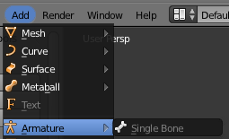
-
Select the bone and go to edit mode (press Tab).
-
Select the root bone end and press E to extrude the bone, then start rigging your model this way.
Make sure your armature’s location, rotation and scale is applied (see “Model Checklist” below) before continuing.
-
-
Make the armature the parent of the model.
-
Make sure you are back in object mode (press Tab again).
-
First select the model object then select the armature object with Shift pressed, then press Ctrl + P.
-
When you do this, you can select how the bone groups will be mapped to the model vertices initially. Select With Automatic Weights.
When you parent your mesh to the armature, Blender automatically adds the
Armaturemodifier to the mesh.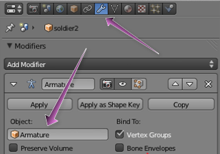
Voila, your model should move when you move the bones in pose mode.
-
-
From the
Infoheader, press the Choose Screen Layout button and select theAnimationlayout. -
In the
Dope Sheet Editorwindow, press the Context button and selectAction Editor.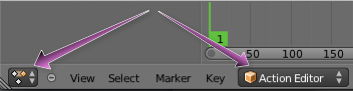
-
Add an action by pressing the + button.
-
Set the “Rotation Mode” of the bone to
Quaternionor switch later from your “Rotation Mode” toQuaternionand make aKeyframe.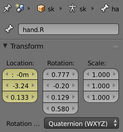
-
Create the
Keyframes (select the model armature and press I) along the timeline.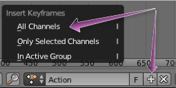
Each action will be an animation available via the animation control in jME after the import.
Press the F button next to the action so it will be saved even if there’s no references. The animation would else be deleted if its not the active animation on the armature and the file is saved.
Model Checklist
Sometimes you do not create the model yourself and often models from the web are not really made for OpenGL live rendering or not completely compatible with the bone system in jME.
To export an animated model in Blender make sure the following conditions are met:
| This checklist is interactive for your convenience. |
-
The animation has to be a bone animation.
-
Apply Location, Rotation and Scale to the mesh in Blender: In the
3D Viewportin Blender, select the mesh inObject Mode, from the3D View Editorheader, click.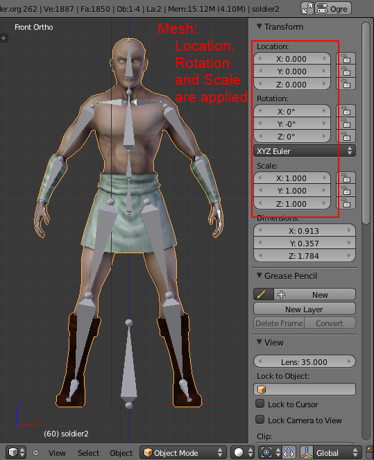
-
Apply Location, Rotation and Scale to the armature in Blender: In the
3D Viewportin Blender, select the armature inObject Mode, from the3D View Editorheader, click.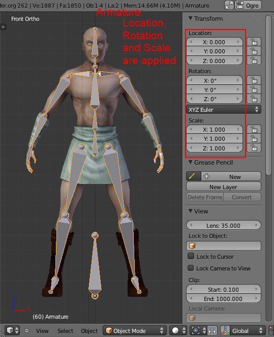
-
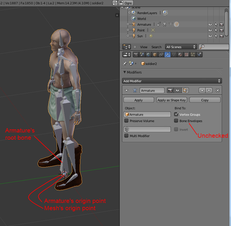
Set the mesh’s origin point in the bottom of the mesh (see the image below).
-
Set the armature’s origin point in the bottom of the armature (see the image below).
-
Armature’s origin point and mesh’s origin point must be in the same location (see the image below).
-
Use a root bone located in the armature’s origin. This root bone must be in vertical position (see the image below) and it is the root bone of the armature. If you rotate the root bone, the entire armature might be rotated when you import the model into jMonkey.
-
Uncheck:
-
Bone Envelopes
on the Armature modifier for the mesh (see the image below).
-
-
Under the armature data tab, make sure the bone type is
Octahedral(see image below).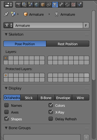
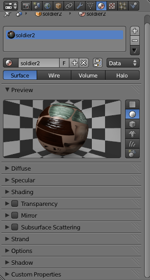
You can use SkeletonDebugger to show the skeleton on your game in order to check if the mesh and the skeleton are loaded correctly:
final Material soldier2Mat = assetManager.loadMaterial("Materials/soldier2/soldier2.j3m");
final Spatial soldier2 = assetManager.loadModel("Models/soldier2/soldier2.j3o");
TangentBinormalGenerator.generate(soldier2);
soldier2.setMaterial(soldier2Mat);

final Node soldier2Node = new Node("Soldier2 Node");

soldier2Node.attachChild(soldier2);
rootNode.attachChild(soldier2Node);

final AnimControl animControl = soldier2.getControl(AnimControl.class);
animControl.addListener(this);
final AnimChannel animChannel = animControl.createChannel();

final SkeletonDebugger skeletonDebug = new SkeletonDebugger("skeleton", animControl.getSkeleton());
final Material mat = new Material(assetManager, "Common/MatDefs/Misc/Unshaded.j3md");
mat.setColor("Color", ColorRGBA.Green);
mat.getAdditionalRenderState().setDepthTest(false);
skeletonDebug.setMaterial(mat);
soldier2Node.attachChild(skeletonDebug);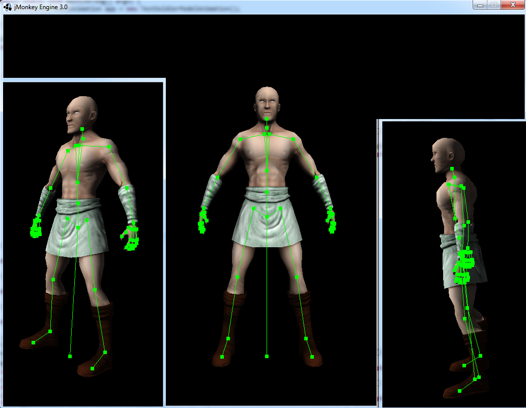
Also check out these videos and resources:
Action Baking
There are many 3D model Supported External File Types for jMonkeyEngine. Some of them bake your actions automatically on export, others don’t. Baking is a destructive process so it is recommended that you test the animation in-game first. If your animations are all messed up, try baking them or use a different exporter.
If you find yourself in need of baking, the process is as follows.
-
From the Blender
Infoheader, select. -
Save the file somewhere other than the current folder. This will save you the effort of re-creating the animation file if you need it at some other time.
-
In the
Infoheader, change theDefaultscreen layout toAnimation. -
In the
Dope Sheet Editor, change theDope Sheetmode/context toAction Editor. -
Click the Action to be linked button and select your action.
-
In the
3d Viewportheader, select the armature.-
Depending on the mode selected choose:
-
Object Mode:
. -
Pose Mode:
.
-
-
-
In the
Bake Actiondialog, deselect and set the settings as follows:- Bake Action
-
-
Selected Only
-
Visual Keying
-
Clear Constraints
-
Clear Parents
-
Overwrite Current - Bake Data = Pose
-
-
When ready click OK.
-
The
Linked Actionin theDope Sheet Editorwill change to the newly baked action and is namedAction. Rename this to the name of the imported animation. -
Select the F button to save the action.
-
Save your file.
-
Clear the old action from the
Linked Actionbuffer. See Blender Buffer Clearing for more information.
Normal Map baking
Models for live rendering should have a low polygon count. To increase the perceived detail of a model, Normal maps are commonly used in games. This tutorial will show how to create a Normal map from a “HighPoly” version of your model that you can apply to a “LowPoly” version of the model in your game.
Blender Modeling LowPoly & HighPoly
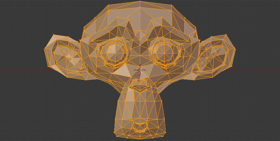
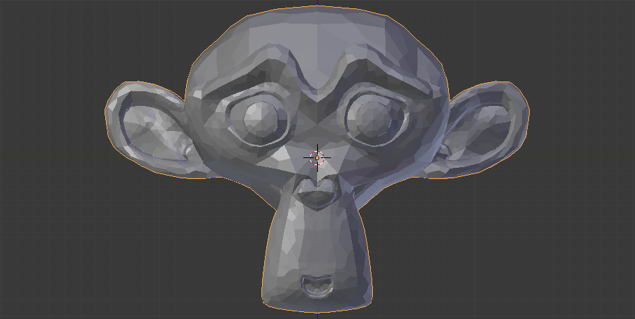
If you use the Multiresolution modifier you only need one object. Let’s look at this example, the Blender object Monkey, with an applied Triangulate modifier:
-
Add a “Monkey” object by selecting the Monkey button located on the “Create Tab”.
-
While in
Object Mode, in thePropertiespanel under theModifierstab, add aTriangulatemodifier and apply it: -
While in
Object Mode, in thePropertiespanel under theModifierstab, add aMultiresolutionmodifier:
There are two types of modifiers: Catmull-Clark and Simple.
-
Simple is better for things like walls or floors.
-
Catmull-Clark is better for objects like spheres.
When using Catmull-Clark with a higher “subdivide” value (more than 3), it’s good to have the “Preview” value above 0 and less than the subdivide level. This is because Catmull-Clark smooths the vertices, so the Normal map is not so precise.
Regardless of the choice, the larger the difference is between “Render” and “Preview”, the deeper the detail is on the Normal map.
-
Here is an example of
Preview 1, it’s more smooth than the original mesh:
-
-
-
From the
Fileheader at the top of the 3d View, click the Choose Screen layout button and select “UV Editing”. -
In the
3d View, select the Monkey and Tab into “Edit Mode”. -
If the Monkey vertices are not already highlighted, press the A key until all vertices are highlighted.
-
From the
3d Viewheader, select.-
Click the Island Margin button once to advance the value to .03.
-
Click OK when ready.
-
-
In the
UV Image Editor, click the New button.-
Change the name to something like “monkey_bump”.
-
Optionally, change the
Generated Typeto “UV Grid”. -
Uncheck:
-
32 Bit
-
-
Click OK when ready.
-
-
From the
Fileheader at the top of theUV Image Editor, click the Choose Screen layout button and select “Default”. -
With your mouse inside the
3D View, tab intoObject Mode. -
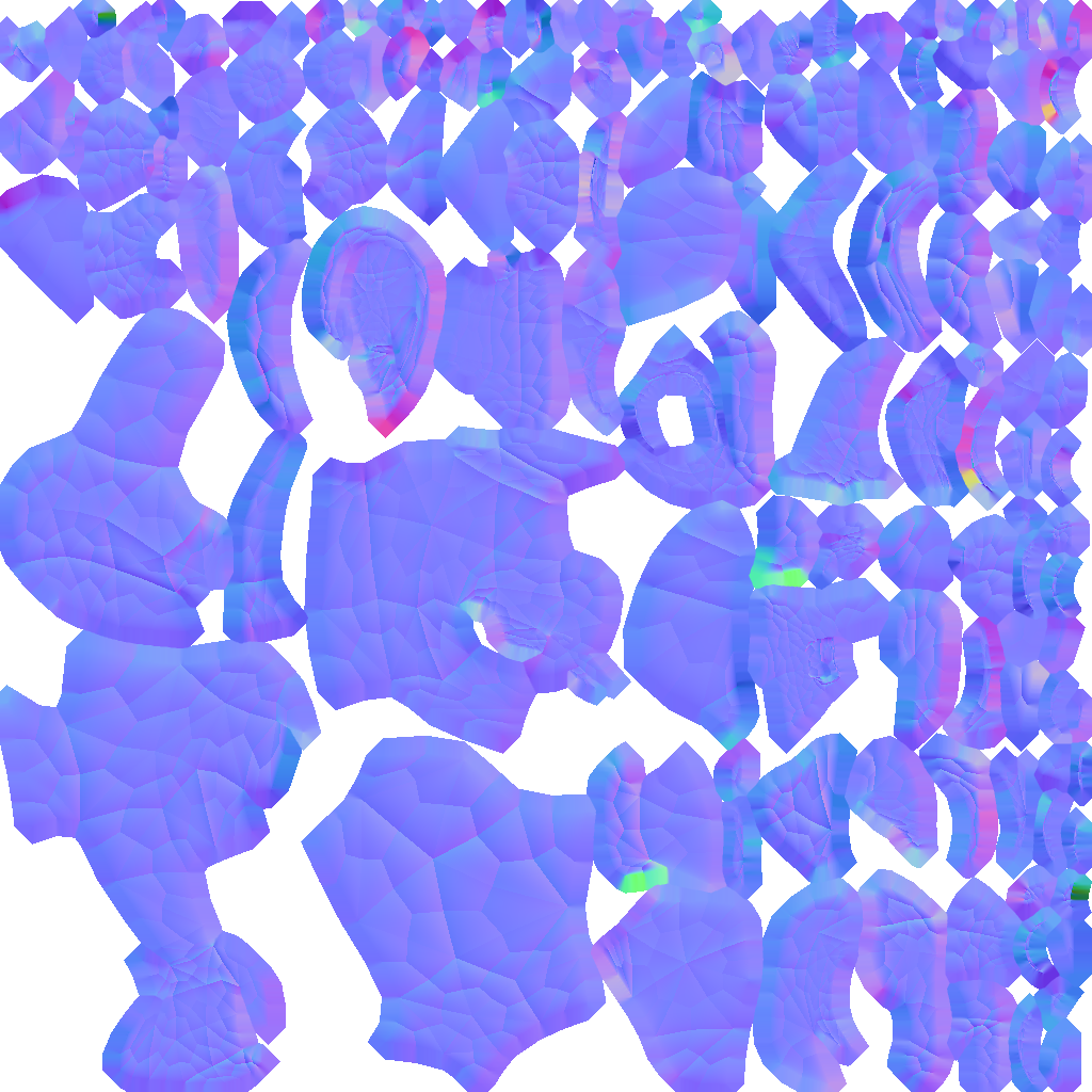
Now go into the
Rendertab, and bake aNormalmap using the same configuration as here:
Remember! The actual preview affects the baking output and mesh export! -
Navigate back to the
UV Editinglayout and save your image by selectingfrom theUV Image Editorheader.
The asterisk * next to the Image menu item means the image has not yet been saved.
|
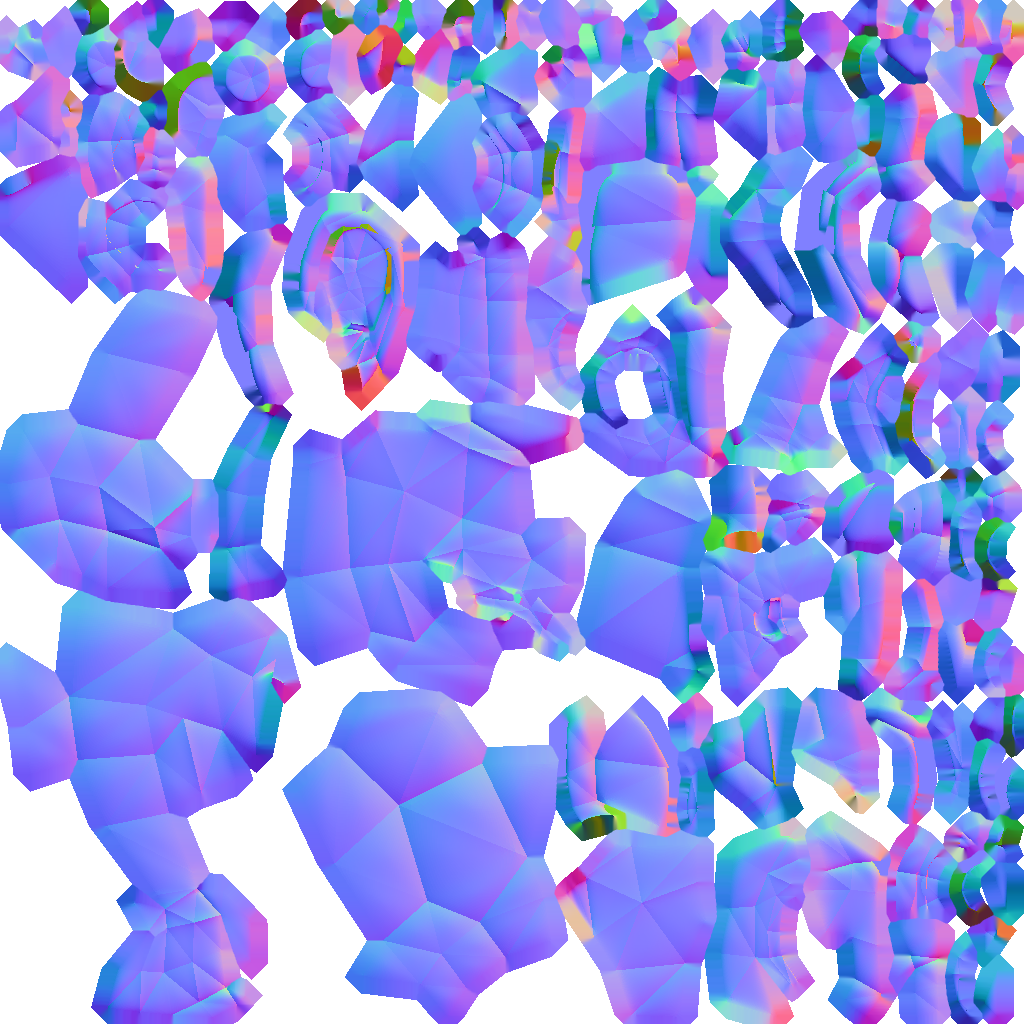
This second method produces the best results by far:
-
Follow the steps for “Method 1” but before baking, uncheck:
-
Bake from Multires
-
-
Make a copy of your mesh (SHIFT+D).
-
Remove the Multires modifier from the copied model.
-
Remove any materials from the copied model.
-
Remove the armature modifier from the copied model.
-
Select the original (HighPoly) model.
-
Go into pose mode, clear any pose transformations.
-
The “HighPoly” and “LowPoly” models should be on top of each other now.
-
Select the original (HighPoly) model.
-
Hold SHIFT and select the copied (LowPoly) model.
-
In the
Propertiespanel, in theRendertab:-
Bake Mode:
Normal -
check:
-
Selected to Active
-
-
Use a reasonably high value for “Margin” (4+ pixels at least for 1024x1024 maps).
-
-
Bake and don’t forget to save the Normal map image.
|
Keep in mind that when you duplicate the model, you are also duplicating its UV mapping. What this means is your "HiPoly" model and “LowPoly” model are both assigned to an image. If you ever see this error: "No objects or images found to bake to" You are either missing the image for the “LowPoly” model, or in the Outliner, the camera symbol (Restrict Render) is off (grayed out). |
Fixing the Normal colors in Blender
There are two “standards” for Normal maps:
-
DirectX
-
OpenGL
The difference between them is that the green channel is inverted. One would expect that JME supports the OpenGL way, but actually JME supports the DirectX way because it’s what Blender supports and the developers of JME thought it would be easier in the Blender to JME workflow.
Because of this, you need to fix the colors to prepare the Normal map for using it with the JME Lighting Material. You should only have to invert the green channel, the red and blue channels should stay unchanged. The curve for the red and blue channels should go from bottom left to top right, the green from top left to bottom right.
To do this after baking and saving the original Normal map image:
-
In the “UV Editing” layout, from the “UV Image Editor” header select
. -
Save the inverted image to a destination you want and use it with the JME Lighting Material and the “LowPoly” version of the model.
|
Inverting Tips
If you build the engine from source, the master branch PBR material has a NormalType parameter that allows one to handle this in the shader instead of having to edit the Normal map. You can also use the SDK to invert the channel:
|
This is what the final outcome of Normal map baking should produce for you. A “LowPoly” model that looks like it’s a “HighPoly” model.
LightMap baking
The goal of this tutorial is to explain briefly how to bake light map in blender with a separate set of texture coordinates and then export a model using this map in jME3.
Blender modeling + texturing
-
create a mesh in blender and unwrap it to create uvs
-
-
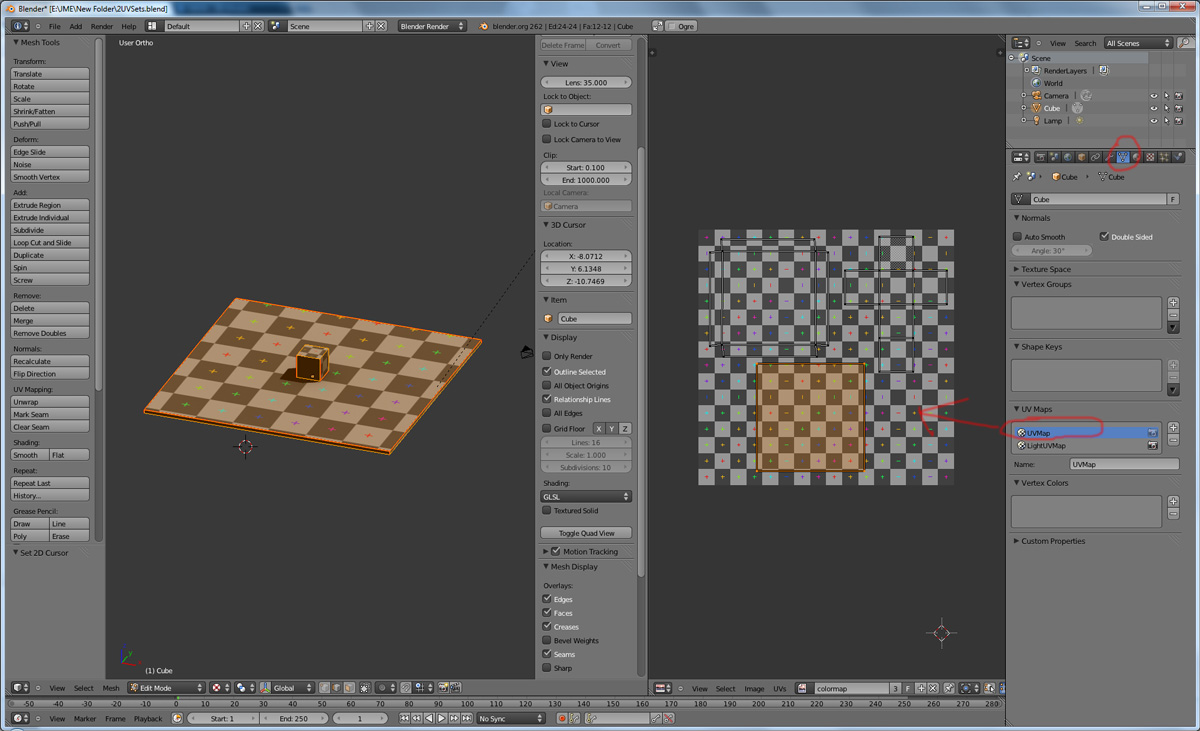
In the mesh tab you can see the sets of Uvs, it will create the first one.
-
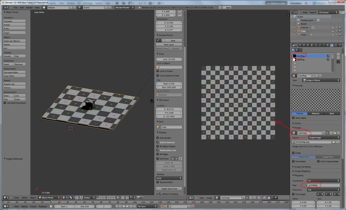
You can assign w/e texture on it, I used the built in checker of blender for the example.
-
-
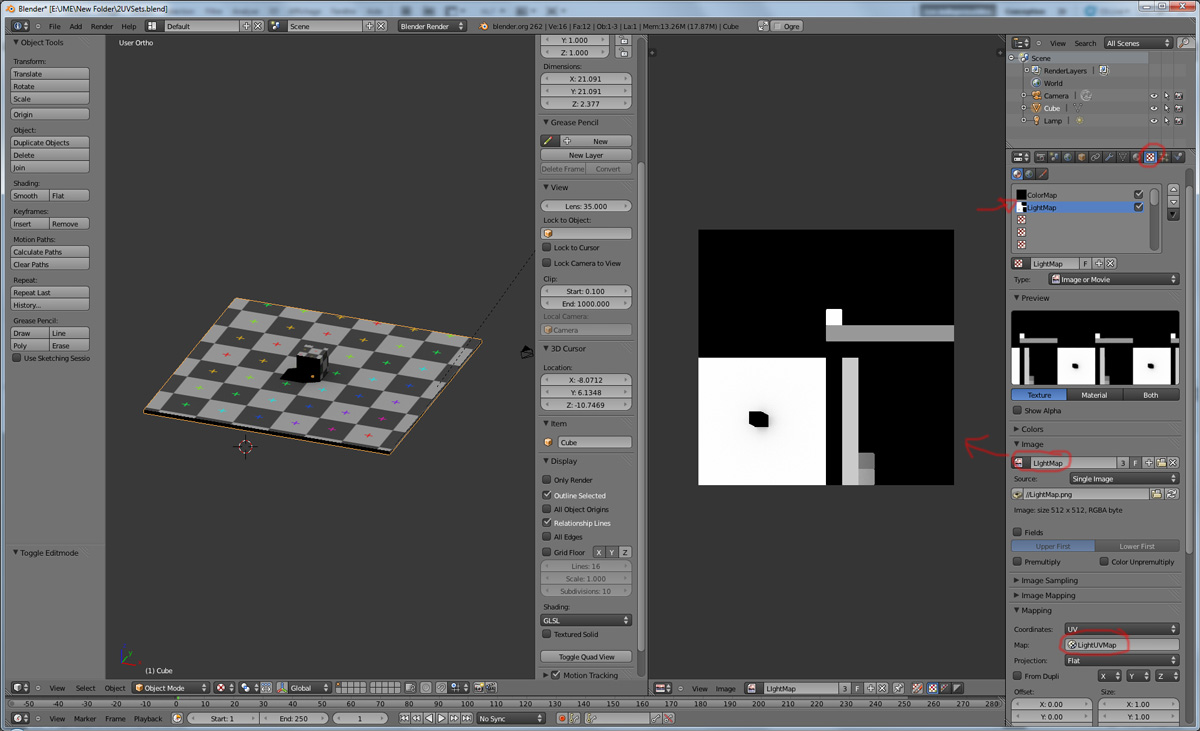
In this list, create a new one and click on the camera icon so that baking is made with this set. Name it LightUvMap.
-
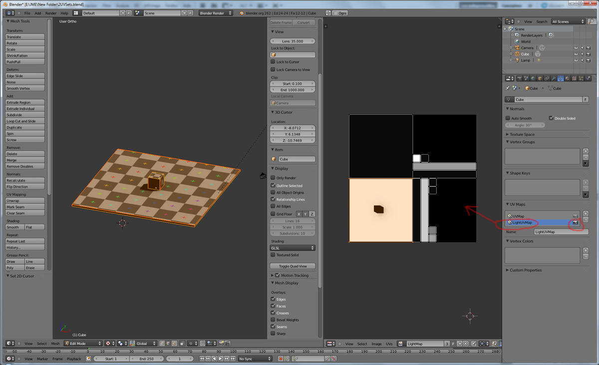
In the 3D view in edit mode select all your mesh vertice and hit 'U'/LightMap pack then ok it will unfold the mesh for light map.
-
Create a new image, go to the render tab an all at the end check the “Bake” section and select shadows. Then click bake.
-
If all went ok it will create a light map like this.
-
-
Go to the material tab, create a new one for your model and go to the Texture Tab.
-
Create 2 textures one for the color map, and one for the light map.
-
In the Mapping section be sure to select coordinates : UV and select the good set of coordinates.
-
-
Then the light map
-
Importing the model in the SDK and creating the appropriate material
Once this is done, export your model with one of the 3D model Supported External File Types and convert it into a .j3o with the SDK, or the JME BinaryExporter.
-
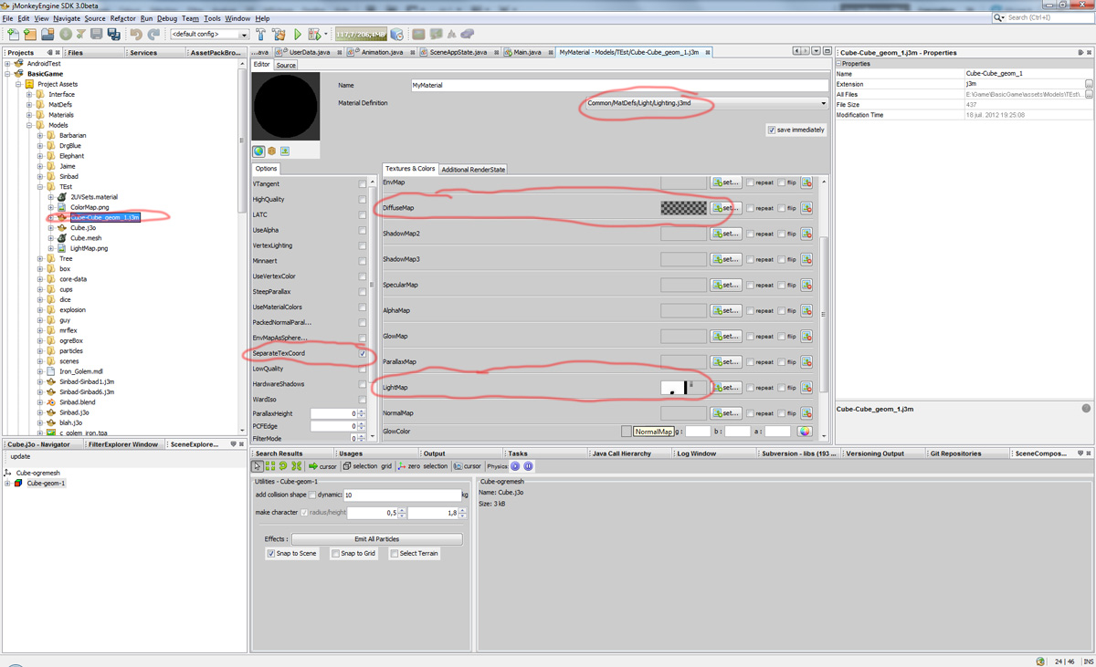
Create material for it using the lighting definition.
-
Add the colorMap in the diffuse map slot and the lightMap in the light map slot.
-
Make sure you check “SeparateTexCoords”
-
-
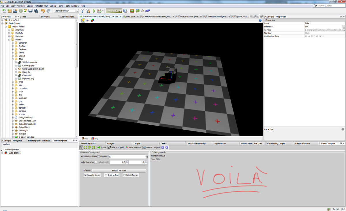
It should roughly result in something like that :
-
Modelling racing tracks and cars
Follow the link below to a pdf tutorial by rhymez where I guide you to modelling a car and importing it to the jMonkeyEngine correctly and edit it in the vehicle editor.Plus how to model a simple racing track. http://www.indiedb.com/games/street-rally-3d/downloads/modelling-in-blender-to-the-jmonkeyengine
Optimizing Models for 3D games
Follow the link below to a pdf tutorial by rhymez where I guide you on how you can optimize your models for faster rendering. http://www.indiedb.com/games/street-rally-3d/downloads/optimizing-3d-models-for-games
SkyBox baking
There are several ways to create static images to use for a sky in your game. This will describe the concepts used in blender and create an ugly sky  . Check the links below for other ways and prettier skies.
A sky box is a texture mapped cube, it can also, loosely, be called en EnvMap or a CubeMap. The camera is inside the cube and the clever thing that jME does is to draw the sky so it is always behind whatever else is in your scene. Imagine the monkey is the camera in the picture.
But a real sky is not a box around our heads, it is more like a sphere. So if we put any old image in the sky it will look strange and might even look like a box. This is not what we want. The trick is to distort the image so that it will look like a sphere even if it in fact is a picture pasted on a box. Luckily blender can do that tricky distortion for us.
The screenshots are from Blender 2.63 but the equivalent operations have been in blender for years so with minor tweaks should work for almost any version.
So let’s get started
-
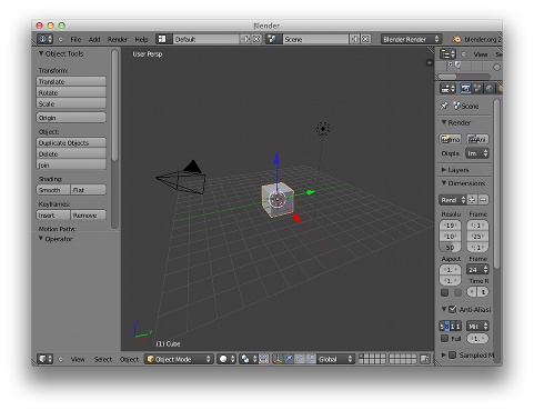
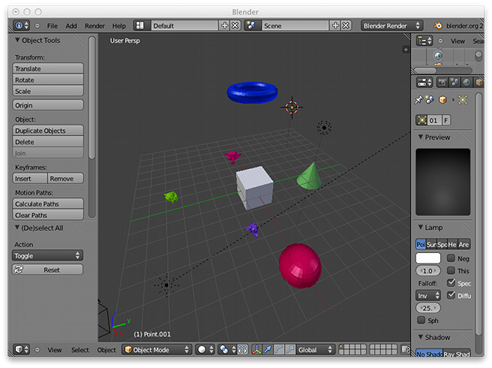
Fire up blender and you’ll see something like this.
-
-
The cube in the start scene is perfect for us. What we’ll do is have Blender render the scene onto that cube. The resulting image is what we’ll use for our sky box. So our jME sky will look like we stood inside the blender box and looked out on the scene in blender.
-
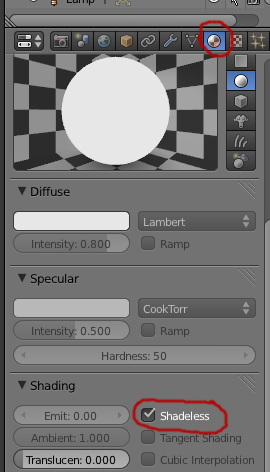
Start by selecting the box and set its material to shadeless.
-
-
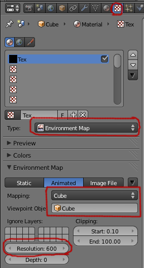
Now we will create a texture for the box. Make sure the texture is an
Environment Map, that theViewpoint Objectis set to the cube. The resolution is how large the resulting image will be. More pixels makes the sky look better but comes at the cost of texture memory. You’ll have to trim the resolution to what works in your application. -
-
Next up is the fun part, create the sky scene in blender. You can do whatever fits your application, include models for a city landscape, set up a texture mapped sphere in blender with a nice photographed sky, whatever you can think will make a good sky. I am not so creative so I created this scene:
-
-
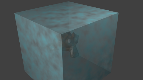
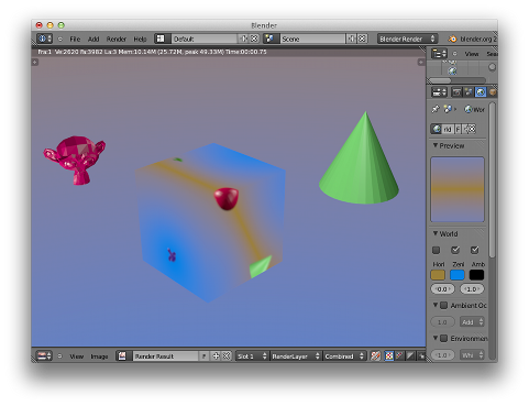
Now render the scene (press F12). It doesn’t actually matter where the camera is in blender but you might see something similar to this:
-
-
You can see that Blender has actually drawn the scene onto the cube. This is exactly what we want. Now to save the image.
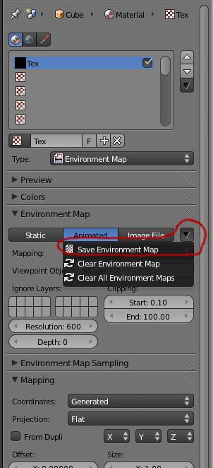
-
Select the texture of the cube and select save environment map.
-
-
That is it for Blender. Open the saved image in some image editor (I use the Gimp from http://www.gimp.org here).
|
The SDK also contains an image editor, right-click the image and select “edit” image to open it. |
-
You will notice that Blender has taken the 6 sides of the cube and pasted together into one image (3x2). So now we need to cut it up again into 6 separate images. In gimp I usually set the guides to where I want to cut and then go into Filters→Web→Slice and let gimp cut it up for me.
-
-
Next up is to move the image files into your assets directory and create the sky in jME. You can do that in the Scene Composer by right clicking the scene node, select
Add Spatialand then selectSkybox.

If you want to do it from code, here is an example:
public void simpleInitApp() {

    Texture westTex = assetManager.loadTexture("Textures/west.png");
    Texture eastTex = assetManager.loadTexture("Textures/east.png");
    Texture northTex = assetManager.loadTexture("Textures/north.png");
    Texture southTex = assetManager.loadTexture("Textures/south.png");
    Texture upTex = assetManager.loadTexture("Textures/top.png");
    Texture downTex = assetManager.loadTexture("Textures/bottom.png");

    final Vector3f normalScale = new Vector3f(-1, 1, 1);
    Spatial skySpatial = SkyFactory.createSky(
                        assetManager,
                        westTex,
                        eastTex,
                        northTex,
                        southTex,
                        upTex,
                        downTex,
                        normalScale);
    rootNode.attachChild(skySpatial);
}|
This example uses a strange normalScale, this is to flip the image on the X-axis and might not be needed in your case. Hint: the texture is applied on the outside of the cube but we are inside so what do we see? |