Introduction to Marine Navigation
This article describes JME’s mercator projection tool. If you don’t know what this means, we suggest you begin by reading The American Practical Navigator or browsing Wikipedia. If you do know what a Mercator projection is, then our “Introduction” to Marine Navigation might serve to refresh your mind.
Wikipedia is a source for formulas shown here. Read it. Absorb it.
Terms, Conventions and Definitions Charts are defined as “graphic” representations of areas of the earth for use in marine or air navigation whereby nautical charts depict features of particular interest to the marine navigator[1].
Prime Meridian designates the Greenwich meridian as of 1884.
Distance is designated in nautical miles whereby one nautical mile corresponds to one meridian arc minute (1,852 metres) at the equator.
Sailing refers to various mathematical methods for determining course, distance, and position. Speed refers to the rate of motion, or distance per unit of time and is measured in knots (kn). One knot is equal to one nautical mile per hour.
Coordinates The purpose of coordinates is to define a distinct position on earth. For the purpose of this project, only latitude and longitude are of importance, although the reader should be aware that other coordinate systems exists such as UMT (Universal Transverse Mercator) and UPS (Universal Polar Stereographic).
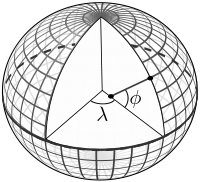
Latitude is the angular distance from the equator, measured northward or southward along a meridian from 0◦ at the equator to 90◦ at the poles[1]. Within aviation and maritime navigation, latitude is designated north (N) or south (S) to indicate the direction of measurement. An equally valid notation designates north (N) to be positive and south (S) to be negative. For example 18◦ N becomes 18 whilst 18◦ S becomes -18. Longitude is the angular distance between the prime meridian and the meridian of a point on the earth, measured eastward or westward from the prime meridian through 180◦. It is designated east (E) or west (W) to indicate the direction of measurement[1] however similar to angular measurements from the equator, may be expressed in terms of negative (W) and positive (S). For ex- ample 18◦ E becomes 18 whilst 18◦ W becomes -18. It is worth noting that degrees can be further subdivided into minutes, whereby one degree equals 60 minutes. Minutes in turn are subdivided into seconds whereby each minute equals 60 seconds. Latitude and longitude coordinates are therefore typically specified as degrees (◦), minutes (’) and seconds (”).
For example: 1◦ 2’ 3” W meaning 1 degree, 2 minutes and 3 seconds West. This in turn can be translated into decimal notation whereby degrees are expressed as a decimal fraction: therefore 1◦ 2’ 3” W would become -1.034167. Alternatively these angular measurements may be converted to radians (in which case they would be expressed as a signed fraction of π). The difference of latitude between two places is the angular length of arc of any meridian between their parallels. That is, it is the numerical difference of the latitudes if the places are on the same side of the equator or the sum of the latitudes if the points are on opposite sides of the equator.[1]
Similarly, the difference of longitude between two places is the shorter arc of the parallel or the smaller angle at the pole between the meridians of the two places. If both places are on the same side (i.e east or west) of Greenwich, then difference of longitude is the numerical difference of the longitudes of the two places; otherwise the difference of longitude is their numerical sum (unless of course this exceeds 180◦. In that case it is 360◦ minus the sum).
Meridional Parts As described by Bowditch, Meridional parts are ”units of latitude that have been adjusted to compensate for the distortion that results from projecting a three-dimensional globe onto a two-dimensional Mercator chart”.
Bearing In marine navigation, bearing is defined as ”the direction one object is from another object, usually, the direction of an object from one’s own vessel”. Note that this is not to be confused with the equivalent term within aviation were bearing refers to ”the actual (corrected) compass direction of the forward course of the aircraft.”
Heading and Course Heading is the direction in which a vessel is pointed and is expressed as degrees from 0 to 359. Course is the over ground track in which a vessel moves. With wind, water movement and steering error, heading and course are not necessary equal.
Mercator Projection Mercator projections are a standard within nautical charts an represent rhumb lines (a.k.a loxodromes) as straight segments. A mercator projection is of non- linear scale as it accounts for distortion in latitude as one moves away from the Equator and towards the poles (with the poles being defined as infinity. This notion is illustrated to the right by figure 1.2). These distortions arise from the fact that the earth is an oblate spheriod i.e. a sphere with a flattened top and bottom (the poles). Therefore, as one moves away from the equator, nautical metrics skew to the extend whereby the length of one degree of latitude along the poles covers approximately 1 percent more distance than at the equator.
Chart Projection
A Mercator projection is defined by its meridians and parallels, both of which are expanded at an equal ratio with increasing latitude. This expansion is due to the distortion that results from projecting an oblate spheroid onto a two- dimensional surface (see introductory notes above) and equates to the secant of the latitude in addition to a correction for this distortion. Note that the secant of 90◦ is infinity, and therefore Mercator projections cannot include the poles (thus the mercator projection employed here stops at 85◦ North and South of the equator).
Rhumb lines appear as straight lines.
The projection calculations are handled by the MapModel2D class, in the case of 2D, and by MapModel3D, in the case of a 3D projection. Fundamentally both projections function in the same manner, with their only real differences being that MapModel3D introduces an extra co-ordinate (z) and the replacement of the toPixel() method with toWorldUnit() which converts a latitude/longitude coordinate object into (x,y,z) world units as opposed to pixel (x,y) coordinates.
The core functionality of the entire system relies on the accurate conversion of latitude/longitude into pixels/world units and vice versa. These conversions are handled by toPixel(), toWorldUnit() and toPosition() respectively.
Note that all sailings used by this class are located inside the NavCalculator class and will be elaborated upon in the next section of this chapter.
Minutes per pixel / Minutes per World Unit
The number of pixels or world units per minute serves as a baseline for all coordinate conversions and is derived by dividing the total number of minutes of longitude composing the chart (i.e. 360 * 60) by the width of the canvas on which to render the projection (aka viewport):
minutesPerPixel = (mapWidthInLongitude * 60) / (double) viewportWidth;
toPixel Unlike commonly assumed, this method is not derived from the inverse Guder- mannian function. Accepting a set of latitude/longitude coordinates encapsulated in a Position object as a parameter, the method returns the equivalent pixel (x, y) encapsulated as a Point object. This conversion can be summarized as follows[2]:
-
Ordered List Item Get the distance between the given position’s longitude coordinate and the chart’s longitude centre.
-
Convert the obtained distance into pixels by dividing it with the number of pixels that are contained within one minute. Refer to it as distanceInPixels.
-
Calculate the x-coordinate by subtracting or adding it to the canvas’ x-centre coordinate (the canvas’ x-centre coordinate being the canvas width di- vided by two) depending on the location of the position itself and the chart’s centre: That is, if the chart is centred west of the prime meridian and if the position to be converted is west of the centre, then the resulting x-coordinate is the difference between the x-centre and the distanceInPixels obtained in step 2 above. If however the centre is West and the position is east of the centre, then the resulting x-coordinate equates to the sum of the x-centre and its dis- tanceInPixels. The opposite is true for an easterly centre and a position west of this centre or an easterly centre and a position east of this centre.
-
Ordered List Item For the y-coordinate, the difference in meridional parts between the chart’s latitude centre and the position’s latitude serves as a baseline. Con- vert the difference to pixels by dividing it by the number of pixels contained
within one minute. Refer to it as dmp1.
-
Ordered List Item Similar to step 3 above, calculate the y-coordinate by subtracting or
adding it to the canvas’ y-centre coordinate (the canvas’ y-centre being the canvas height divided by two) depending on the location of the position itself and the chart’s centre: That is, if the centre is north and the position is north of the centre, then the resulting y-coordinates equates to the difference between dmp and the y-centre coordinate. If however the centre is north but the position is south of the centre, then the resulting y-coordinate equates to their sum. The opposites are true given that the centre lies in the southern hemisphere.
The following converts a latitude/longitude coordinate pair into a JME world-unit vector:
try {
    int worldWidth = 800;
    MapModel3D m = new MapModel3D(worldWidth);
    Vector3f v = m.toWorldUnit(new Position(-53, 8.0));
} catch (InvalidPositionException e) { e.printStackTrace(); }
To convert world units into latitude/longitude coordinates, use the map model’s toPosition method:
try {
     int worldWidth = 800; MapModel3D m = new MapModel3D(worldWidth);
     Position pos = m.toPosition(new Vector3f(10, 10, 10));
     System.out.println("Latitude: " + pos.getLatitude() + " Longitude: " + pos.getLongitude());
} catch (InvalidPositionException e) {
     e.printStackTrace();
}
Navigational calculations are performed inside the NavCalculator class.
Mercator Sailing Mercator sailing is defined as ’the process of solving problems involving course, distance, difference of latitude and difference of longitude, by considering them in relation to a Mercator chart’[1]. Essentially, this refers to the plotting of a rhumb line2 on a Mercator chart whereby the rhumb line will appear as a straight line. That is, given a constant bearing β north of the rhumb line, longitude λ0 where the line passes the equator, λ1 being any longitude point of the rhumb line, and φ being any latitude point on the rhumb line then its Mercator projection can be derived as:
-
x = λ1
-
y = m(λ1 − λ0)
where slope m is cot(β), then λ and φ can be expressed as
-
x = λ1
-
y = tanh−1(sin(φ) φ = sin−1(tanh(m(λ1 − λ0)))
That is, tan(course) = (differenceinlongitude)/(differenceinmeridionalparts) and distance = (differenceinlatitude/cos(course)) where the difference in meridional parts is defined in terms of a Clarke Spheroid.
This is implemented as follows where RLSailing and Position are wrapper classes.
public RLSailing mercatorSailing(Position p1, Position p2) {
     double dLat = computeDLat(p1.getLatitude(), p2.getLatitude());
     if (dLat == 0) {
          RLSailing rl = planeSailing(p1, p2); return rl;
     }
     double dLong = computeDLong(p1.getLongitude(), p2.getLongitude());
     double dmp = (float) computeDMPClarkeSpheroid(p1.getLatitude(), p2.getLatitude());
     trueCourse = (float) Math.toDegrees(Math.atan(dLong / dmp));
     double degCrs = convertCourse((float) trueCourse, p1, p2);
     distance = (float) Math.abs(dLat / Math.cos(Math.toRadians(trueCourse)));

     RLSailing rl = new RLSailing(degCrs, (float) distance);
     trueCourse = rl.getCourse();
     return rl;
}
where dmp refers to the difference in meridional parts.
Difference in Meridional Parts Meridional parts are units of latitude that have been adjusted to compensate for the distortion that results from projecting an oblate spheroid onto a two- dimensional surface.
Although other datums (such as WGS 84) are equally valid, the navigation module performs all calculations within the context of the Clarke spheroid of 1880 which has an equatorial radius of 6,378,249.145 meters, a polar radius of 6,356,514.870 meters and an inverse flattening of 293.465 meters. The meridional part for any latitude L is therefore defined as: M = 7915.704468 ∗ log(tan(45 + (L/2))) − 23.268932 ∗ (sin(L)) − 0.052500 ∗ (sin(L))3 − 0.000213 ∗ (sin(L))5
Where m1 and m2 refer to the meridional parts of the offset and destination point respectively, the difference of meridional parts is calculated as |m1 − m2| if both points are north, or south of the equator or as their sum if one of the points is north and the other south of the equator:
public static double computeDMPClarkeSpheroid(double lat1, double lat2) {
     double absLat1 = Math.abs(lat1); double absLat2 = Math.abs(lat2);
     double m1 = (7915.704468 * (Math.log(Math.tan(Math.toRadians(45 + (absLat1 / 2)))) / Math.log(10)) - 23.268932 * Math.sin(Math.toRadians(absLat1)) - 0.052500 * Math.pow(Math.sin(Math.toRadians(absLat1)), 3) - 0.000213 * Math.pow(Math.sin(Math.toRadians(absLat1)), 5));
double m2 = (7915.704468 * (Math.log(Math.tan(Math.toRadians(45 + (absLat2 / 2)))) / Math.log(10))
- 23.268932 * Math.sin(Math.toRadians(absLat2)) - 0.052500 * Math.pow(Math.sin(Math.toRadians(absLat2)), 3) - 0.000213 * Math.pow(Math.sin(Math.toRadians(absLat2)), 5));
     if ((lat1 <= 0 && lat2 <= 0) || (lat1 > 0 && lat2 > 0)) {
          return Math.abs(m1 - m2);
     } else {
          return m1 + m2;
     }
}
Course Conversion
The conversion of a true course to its equivalent compass course (i.e. con- version of true course to the targets course over ground (COG) where ’true course’ is defined as the course to be steered from true north3) as used by the mercatorSailing method is achieved by subtracting the course variation from the true course, where variation is the angular difference between true north and the direction of the Earth’s magnetic field (consequently variation is termed East or West depending on the target’s position relative to true north).
Given the true course between two positions, the COG is calculated by calling NavCalculator.convertCourse(tc, p1, p2)
Difference in Latitude
The difference in latitude depends on the hemisphere in which both positions are can be determined by calling NavCalculator.computeDLat(lat1, lat2).
Difference in Longitude Similar to the difference in latitude, the difference in longitude depends on which side of the prime meridian both positions are in and can be determined by calling NavCalculator.computeDLong(long1, long2).
Bearing The direction that one target is from another. Given the latitude of two points (φ0andφ1) and the longitude of two points(λ0andλ1), bearing (θ) is defined as follows: Let dLon be the difference in longitude of λ0andλ1, then
-
x = (sin(dLon) ∗ cos(φ1)
-
y = cos(φ0) ∗ sin(φ1) − sin(φ0) ∗ cos(φ1) ∗ cos(dLon))
-
θ = 2arctan√ θ = atan2(y, x)
-
y
x2+y2+x
Which can be determined as follows:
try {
     double bearing = NavCalculator.computeBearing(new Position(-53.6, 8.1), new Position(-53, 8.
  } catch (InvalidPositionException e) {
     e.printStackTrace();
  }
[1] Nathaniel Bowditch (1995), The American Practical Navigator,. United States Government, National Ocean Service Publishing. [2] Gebruers C., “JMarine”