Custom Mesh Shapes
Use the Mesh class to create custom shapes that go beyond Quad, Box, Cylinder, and Sphere, even procedural shapes are possible. Thank you to KayTrance for providing the sample code!
|
In this tutorial, we (re)create a very simple rectangular mesh (a quad), and we have a look at different ways of coloring it. Coding a custom quad may not be very useful because it’s exactly the same as the built-in |
-
Full code sample: TestCustomMesh.java
Polygon Meshes
Polygon meshes are made up of triangles. The corners of the triangles are called vertices. When ever you create any new shape, you break it down into triangles.
Example: Let’s look at a cube. A cube is made up of 6 rectangles. Each rectangle can be broken down into two triangles. This means you need 12 triangles to describe a cube mesh. Therefor you must provide the coordinates of the triangles' 8 corners (called vertices).
The important thing is that you have to specify the vertices of each triangle in the right order: Each triangle separately, counter-clockwise.
Sounds harder than it is – let’s create a simple custom mesh, a quad.
Creating a Quad Mesh
In this tutorial we want to create a 3x3 Quad. The quad has four vertices, and is made up of two triangles. In our example, we decide that the bottom left corner is at 0/0/0 and the top right is at 3/3/0.
0,3,0--3,3,0
| \        |
|   \      |
|     \    |
|       \  |
|         \|
0,0,0--3,0,0
The Mesh Object
The base class for creating meshes is com.jme3.scene.Mesh.
Mesh mesh = new Mesh();|
If you create your own Mesh-based class ( |
Vertex Coordinates
To define your own shape, determine the shape’s vertex coordinates in 3D space. Store the list of corner positions in an com.jme3.math.Vector3f array. For a Quad, we need four vertices: Bottom left, bottom right, top left, top right. We name the array vertices[].
Vector3f [] vertices = new Vector3f[4];
vertices[0] = new Vector3f(0,0,0);
vertices[1] = new Vector3f(3,0,0);
vertices[2] = new Vector3f(0,3,0);
vertices[3] = new Vector3f(3,3,0);
Texture Coordinates
Next, we define the Quad’s 2D texture coordinates for each vertex, in the same order as the vertices: Bottom left, bottom right, top left, top right. We name this Vector2f array texCoord[]
Vector2f[] texCoord = new Vector2f[4];
texCoord[0] = new Vector2f(0,0);
texCoord[1] = new Vector2f(1,0);
texCoord[2] = new Vector2f(0,1);
texCoord[3] = new Vector2f(1,1);
This syntax means, when you apply a texture to this mesh, the texture will fill the quad from corner to corner at 100% percent size. Especially when you stitch together a larger mesh, you use this to tell the renderer whether, and how exactly, you want to cover the whole mesh. E.g. if you use .5f or 2f as texture coordinates instead of 1f, textures will be stretched or shrunk accordingly.
Connecting the Dots
Next we turn these unrelated coordinates into triangles: We define the order in which each triangle is constructed. Think of these indexes as coming in groups of three. Each group of indexes describes one triangle. If the corners are identical, you can (and should!) reuse an index for several triangles.
Remember that you must specify the vertices counter-clockwise.
int [] indexes = { 2,0,1, 1,3,2 };This syntax means:
-
The indices 0,1,2,3 stand for the four vertices that you specified for the quad in
vertices[]. -
The 2,0,1 triangle starts at top left, continues bottom left, and ends at bottom right.
-
The 1,3,2 triangle start at bottom right, continues top right, and ends at top left.
2\2--3
| \  | Counter-clockwise
|  \ |
0--1\1
If the shape is more complex, it has more triangles, and therefor also more vertices/indices. Just continue expanding the list by adding groups of three indices for each triangle. (For example a three-triangle “house” shape has 5 vertices/indices and you’d specify three groups: int [] indexes = { 2,0,1, 1,3,2, 2,3,4 };.)
|
If you get the order wrong (clockwise) for some of the triangles, then these triangles face backwards. If the Spatial's material uses the default |
Setting the Mesh Buffer
You store the Mesh data in a buffer.
-
Using
com.jme3.util.BufferUtils, we create three buffers for the three types of information we have:-
vertex coordinates,
-
texture coordinates,
-
indices.
-
-
We assign the data to the appropriate type of buffer inside the
Meshobject. The three buffer types (Position,TextCoord,Index) are taken from an enum incom.jme3.scene.VertexBuffer.Type. -
The integer parameter describes the number of components of the values. Vertex positions are 3 float values, texture coordinates are 2 float values, and the indices are 3 ints representing 3 vertices in a triangle.
-
To render the mesh in the scene, we need to pre-calculate the bounding volume of our new mesh: Call the
updateBound()method on it.
mesh.setBuffer(Type.Position, 3, BufferUtils.createFloatBuffer(vertices));
mesh.setBuffer(Type.TexCoord, 2, BufferUtils.createFloatBuffer(texCoord));
mesh.setBuffer(Type.Index,    3, BufferUtils.createIntBuffer(indexes));
mesh.updateBound();
Our Mesh is ready! Now we want to see it.
Using the Mesh in a Scene
We create a com.jme3.scene.Geometry and com.jme3.material.Material from our mesh, apply a simple color material to it, and attach it to the rootNode to make it appear in the scene.
Geometry geo = new Geometry("OurMesh", mesh); // using our custom mesh object
Material mat = new Material(assetManager,
    "Common/MatDefs/Misc/Unshaded.j3md");
mat.setColor("Color", ColorRGBA.Blue);
geo.setMaterial(mat);
rootNode.attachChild(geo);
Library for assetManager? Ta-daa!
Using a Quad instead
We created a quad Mesh it can be replace by a Quad such as :
Quad quad = new Quad(1,1); // replace the definition of Vertex and Textures Coordinates plus indexes
Geometry geo = new Geometry("OurQuad", quad); // using Quad object
Material mat = new Material(assetManager,
    "Common/MatDefs/Misc/Unshaded.j3md");
mat.setColor("Color", ColorRGBA.Blue);
geo.setMaterial(mat);
rootNode.attachChild(geo);
If you want to change the Textures Coordinates, in order to change the scale of the texture, use :
Quad quad = new Quad(1,1);
quad.scaleTextureCoordinates(new Vector2f(width , height));
Dynamic Meshes
If you are modifying a mesh dynamically in a way which changes the model’s bounds, you need to update it:
-
Call
updateBound()on the mesh object, or -
Call
updateModelBound()on the Geometry object containing the mesh - which in turns callsupdateBound()on the mesh.
The updateModelBound() method warns you about not usually needing to use it, but that can be ignored in this special case.
N.B.: This does not work on TerrainQuad. Please use the TerrainQuad.adjustHeight() function to edit the TerrainQuad mesh instead. Additionally, if you want to use collisions on them afterwards, you need to call TerrainPatch.getMesh().createCollisionData(); to update the collision data, else it will collide with what seems to be the old mesh.
Optional Mesh Features
There are more vertex buffers in a Mesh than the three shown above. For an overview, see also mesh.
Example: Vertex Colors
Vertex coloring is a simple way of coloring meshes. Instead of just assigning one solid color, each vertex (corner) has a color assigned. The faces between the vertices are then colored with a gradient. For this demo, you can use the same mesh mesh object that you defined above.
Geometry geo = new Geometry ("ColoredMesh", mesh); // using the custom mesh
Material matVC = new Material(assetManager, "Common/MatDefs/Misc/Unshaded.j3md");
matVC.setBoolean("VertexColor", true);
You create a float array color buffer:
-
Assign 4 color values, RGBA, to each vertex.
-
To loop over the 4 color values, use a color index
-
int colorIndex = 0;
-
The color buffer contains four color values for each vertex.
-
The Quad in this example has 4 vertices.
-
float[] colorArray = new float[4*4];
-
Tip: If your mesh has a different number of vertices, you would write:
float[] colorArray = new float[yourVertexCount * 4]
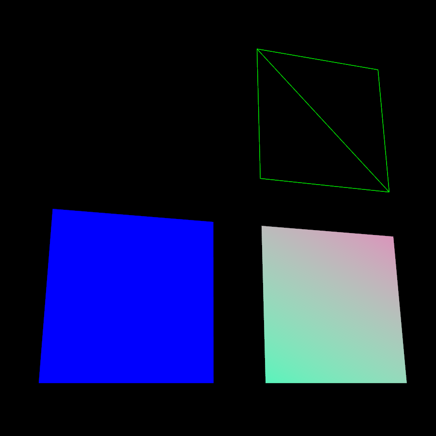
Loop over the colorArray buffer to quickly set some RGBA value for each vertex. As usual, RGBA color values range from 0.0f to 1.0f. Note that the color values in this example are arbitrarily chosen. It’s just a quick loop to give every vertex a different RGBA value (a purplish gray, purple, a greenish gray, green, see screenshot), without writing too much code. For your own mesh, you’d assign meaningful values for the color buffer depending on which color you want your mesh to have.
// note: the red and green values are arbitrary in this example
for(int i = 0; i < 4; i++){
   // Red value (is increased by .2 on each next vertex here)
   colorArray[colorIndex++]= 0.1f+(.2f*i);
   // Green value (is reduced by .2 on each next vertex)
   colorArray[colorIndex++]= 0.9f-(0.2f*i);
   // Blue value (remains the same in our case)
   colorArray[colorIndex++]= 0.5f;
   // Alpha value (no transparency set here)
   colorArray[colorIndex++]= 1.0f;
}
Next, set the color buffer. An RGBA color value contains four float components, thus the parameter 4.
mesh.setBuffer(Type.Color, 4, colorArray);
geo.setMaterial(matVC);
When you run this code, you see a gradient color extending from each vertex.
Example: Using Meshes With Lighting.j3md
The previous examples used the mesh together with the Unshaded.j3md material. If you want to use the mesh with a Phong illuminated material (such as Lighting.j3md), the mesh must include information about its Normals. (Normal Vectors encode in which direction a mesh polygon is facing, which is important for calculating light and shadow!)
float[] normals = new float[12];
normals = new float[]{0,0,1, 0,0,1, 0,0,1, 0,0,1};
mesh.setBuffer(Type.Normal, 3, BufferUtils.createFloatBuffer(normals));
You need to specify as many normals as the polygon has vertices. For a flat quad, the four normals point in the same direction. In this case, the direction is the Z unit vector (0,0,1), this means our quad is facing the camera.
If the mesh is more complex or rounded, calculate cross products of neighbouring vertices to identify normal vectors!
Example: Point Mode
Additionally to coloring the faces as just described, you can hide the faces and show only the vertices as colored corner points.
Geometry coloredMesh = new Geometry ("ColoredMesh", cMesh);
...
mesh.setMode(Mesh.Mode.Points);
mesh.updateBound();
mesh.setStatic();
Geometry points = new Geometry("Points", mesh);
points.setMaterial(mat);
rootNode.attachChild(points);
rootNode.attachChild(geo);
This will result in a 10 px dot being rendered for each of the four vertices. The dot has the vertex color you specified above. The Quad’s faces are not rendered at all in this mode. You can use this to visualize a special debugging or editing mode in your game.
Debugging Tip: Culling
By default, jME3 optimizes a mesh by “backface” culling, this means not drawing the inside. It determines the side of a triangle by the order of the vertices: The frontface is the face where the vertices are specified counter-clockwise.
This means for you that, by default, your custom mesh is invisible when seen from “behind” or from the inside. This may not be a problem, typically this is even intended, because it’s faster. The player will not look at the inside of most things anyway. For example, if your custom mesh is a closed polyhedron, or a flat wallpaper-like object, then rendering the backfaces (the inside of the pillar, the back of the painting, etc) would indeed be a waste of resources.
In case however that your usecase requires the backfaces be visible, you have two options:
-
If you have a very simple scene, you can simply deactivate backface culling for this one mesh’s material.
mat.getAdditionalRenderState().setFaceCullMode(FaceCullMode.Off);
-
Another solution for truly double-sided meshes is to specify each triangle twice, the second time with the opposite order of vertices. The second (reversed) triangle is a second frontface that covers up the culled backface.
int[] indexes = { 2,0,1, 1,3,2, 2,3,1, 1,0,2 };
See also:
-
Spatial – contains more info about how to debug custom meshes (that do not render as expected) by changing the default culling behaviour.
-
mesh[Mesh] – more details about advanced Mesh properties